Train Automation
A collection of programs and hardware simulating railroad operations.
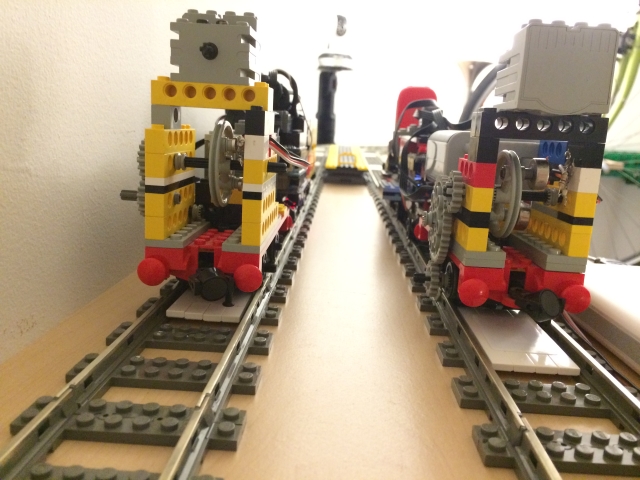
Prototype completed, October 2017, Brooklyn, NY.
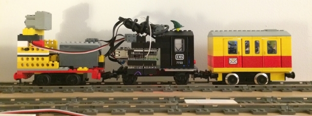
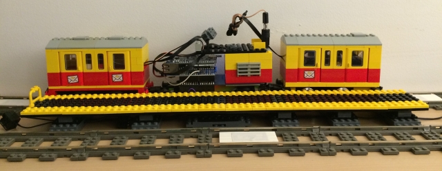
Proof-of-concept demo, October 2015, Lower East Side.
Automatic Train Control (ATC) has three parts:
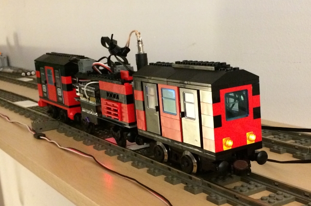
The Virtual Train Operator, which runs the train, stops at stations, and stops at "red signals." The VTO is represented by an arduino sketch.
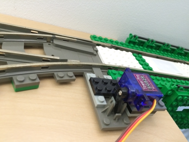
Automatic Train Protection (ATP), a type "virtual signalling system." The ATP program runs on a computer server. It maintains a representation of the track layout and continually searches the path in front of a train for obstacles. Obstacles include a train, switch, or "dispatcher red signal."
The Virtual Dispatcher, a simple logic engine that interprets a program created by the user. A statement might be composed of "if the bedroom line is occupied by one southbound train, set the south switch to straight." A collection of such statements compose a program, which can safely route trains on intersecting paths through the track.
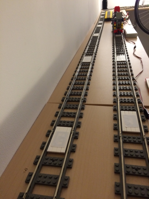
Proof-of-concept demo, October 2015, LES, southbound.
Proof-of-concept demo, October 2015, LES, bird's eye view.
The project touches many interests, including public transportation, the internet of things, event-driven application design, railroad signaling, logic, and a fascination with the lego brand.
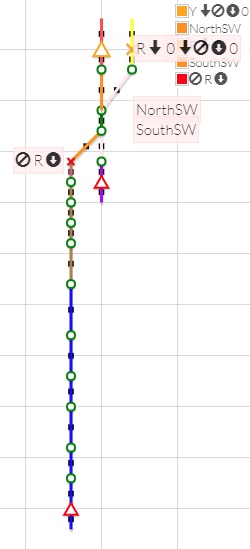
The track is represented by a doubly-linked list, and is displayed on a flot graph. Shown here is the layout used to test the completed prototype.
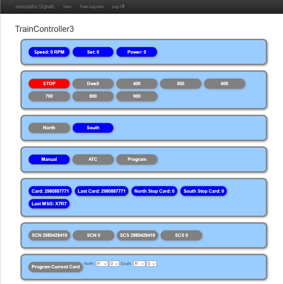
Trains can be controlled directly with this user interface. Built before I had learned bootstrap, it stubbornly persists because it's responsive just enough to be used on a modern smartphone.